Hi All
I have one Structural Enterprise license. along one time, I used 3 software (STAAD.Pro, Staad Foundation and Advanced Steel RAM). I have been counted Over Usage is not ?
Hi All
I have one Structural Enterprise license. along one time, I used 3 software (STAAD.Pro, Staad Foundation and Advanced Steel RAM). I have been counted Over Usage is not ?
When trying to import an S2K file from SAP 2000 into Ram Elements I get the following error messages (see screen shot below).
They all relate to "an item with ID "X" referenced by table COMBINATION DEFINITIONS does not exist in LOAD CASE DEFINITIONS".
This is in RAM Elements 13.3.0.117. The S2K file is from SAP 2000 version 16.
Is there a way to fix this or do something in the SAP model before exporting?
The TechNotes and FAQs in this section cover various topics that pertain to RAM Structural System. Use the navigation tree on the left or the popular links below to browse.
| Applies To | |||
| Product(s): | RAM Structural System | ||
| Version(s): | 14.06.02.00 | ||
| Environment: | all | ||
| Area: | ISM | ||
| Original Author: | Seth Guthrie, Bentley Technical Support Group | ||
When using the RAM Manager - ISM - New from repository, RAM Manager may crash and no model is generated.

In some cases the problem is limited to complex structures where the generation of additional nodes causes an exception. To rule this out, step through the import process again, and on the second screen of options called "operation Settings" uncheck the first option on the left to "Add missing nodes"

If the process still crashes, send the repository to the technical support group through a forum post or Service Request and reference this article.
![]()
| Applies To | |||
| Product(s): | RAM Structural System, RAM Elements, RAM Connection, RAM Concept, STAAD.Pro | ||
| Version(s): | V8i | ||
| Environment: | N/A | ||
| Area: | N/A | ||
| Subarea: | N/A | ||
| Original Author: | Bentley Technical Support Group | ||
Various program anomalies can be solved by conducting a procedure called a clean installation. This involves uninstalling all versions of a program and removing any files that are left behind prior to reinstalling. Following are instructions for doing this for specific Structural products.
Before doing these steps, please make copies of any custom tables that have been added to the program. These typically reside in one of the following locations:
C:\Program Files\Bentley\Engineering\RAM Structural System\Tables
C:\Program Files\Ram\RAM Structural System\Tables
C:\Documents and Settings\All Users\Application Data\Bentley\Engineering\RAM Structural System\Tables (Windows XP only)
C:\ProgramData\Bentley\Engineering\RAM Structural System\Tables (Windows Vista/7 only)
Ensure that none of your models are saved within the RAM Structural System folder. Finally, if you have made extensive modifications to your user defaults, please make a copy of your RamIS.ini file. This can be located in one of two places depending upon your operating system:
Windows XP - C:\Documents and Settings\All Users\Application Data\Bentley\Engineering\RAM Structural System
Windows Vista/7 - C:\ProgramData\Bentley\Engineering\RAM Structural System
The defaults can be copied into the new configuration file later on, if needed.
Select Control Panel from the Windows Start menu, and open either Add or Remove Programs (Windows XP) or Programs and Features (Windows Vista/7). Uninstall all listings for RAM Structural System, starting with the most recent. Then, remove any RAM Structural System folders residing in the following locations (if they exist):
C:\Program Files\Bentley\Engineering
C:\Program Files\Ram
C:\Documents and Settings\All Users\Application Data\Bentley\Engineering (Windows XP only)
C:\ProgramData\Bentley\Engineering (Windows Vista/7 only)
Now navigate to C:\Windows and remove any files beginning with RAMIS (if they exist). Finally, reinstall RAM Structural System. After installation, copy any custom tables to the Tables folder. The default location for the Tables directory in RAM Structural System 14.03.xx.xx and later is in one of two places, depending on the operating system:
Windows XP - C:\Documents and Settings\All Users\Application Data\Bentley\Engineering\RAM Structural System\Tables
Windows Vista/7 - C:\ProgramData\Bentley\Engineering\RAM Structural System\Tables
If the RamIS.ini file was saved to preserve user defaults, please open this file and copy everything but the [Directories] section (usually ends with a line beginning with "working=".) Locate the new RamIS.ini file which will be saved in one of two locations depending on your operating system:
Windows XP - C:\Documents and Settings\All Users\Application Data\Bentley\Engineering\RAM Structural System
Windows Vista/7 - C:\ProgramData\Bentley\Engineering\RAM Structural System
Open the new RamIS.ini file, select everything but the [Directories] section, and then paste the settings copied earlier into the new file. Save changes, and close the file.
Before doing these steps, please back up any custom sections, materials, connections, bolts, and welds as well as any user-created models. The custom sections, materials, connections, bolts, and welds are stored in the Database folder located in one of two locations below. Back up any user-created models that may be saved in the Data folder in one of the two locations below.
Version 13.0.3 and earlier:
C:\Documents and Settings\All Users\Application Data\Bentley\Engineering\RAM Elements (Windows XP)
C:\ProgramData\Bentley\Engineering\RAM Elements (Windows Vista/7)
Version 13.2.0 and later:
C:\ProgramData\Bentley\Engineering\RAM Elements.en (Windows Vista/7 - English Version)
C:\ProgramData\Bentley\Engineering\RAM Elements.es (Windows Vista/7 - Spanish Version)
Important: The Database folder in C:\Program Files\Bentley\Engineering\RAM Elements contains standard elements that come with the program. It does not contain any user-created custom sections, materials, connections, bolts or welds.
Select Control Panel from the Windows Start menu, and open either Add or Remove Programs (Windows XP) or Programs and Features (Windows Vista/7). Uninstall all listings for RAM Elements, starting with the most recent. If any listings for RAM Advanse are present, remove these as well. Then, remove any RAM Elements, RAM Elements.en, RAM Elements.es, or RAM Advanse folders residing in the following locations (if they exist):
C:\Program Files\Bentley\Engineering
C:\Program Files\Ram
C:\Documents and Settings\All Users\Application Data\Bentley (Windows XP only)
C:\Documents and Settings\All Users\Application Data\Bentley\Engineering (Windows XP only)
C:\ProgramData\Bentley (Windows Vista/7 only)
C:\ProgramData\Bentley\Engineering (Windows Vista/7 only)
%USERPROFILE%\Application Data\Bentley\Engineering (Windows XP only)
%USERPROFILE%\AppData\Roaming\Bentley\Engineering (Windows Vista/7 only)
Finally, reinstall RAM Elements. Restore any custom sections, materials, connections, bolts, and welds by moving the Database folder back to the RAM Elements folder located in one of the two locations below. User-created models that were previously backed up can be restored to the Data folder in one of the two locations below as well, although they can be opened from anywhere.
Version 13.0.3 and earlier:
C:\Documents and Settings\All Users\Application Data\Bentley\Engineering\RAM Elements (Windows XP)
C:\ProgramData\Bentley\Engineering\RAM Elements (Windows Vista/7)
Version 13.2.0 and later:
C:\ProgramData\Bentley\Engineering\RAM Elements.en (Windows Vista/7 - English Version)
C:\ProgramData\Bentley\Engineering\RAM Elements.es (Windows Vista/7 - Spanish Version))
Before doing these steps, please back up any custom sections, materials, connections, bolts, and welds as well as any user-created models. The custom sections, materials, connections, bolts, and welds are stored in the Database folder located in one of two locations below. Back up any user-created models that may be saved in the Data folder in one of the two locations below.
RAM Connection v8.0.1 and earlier:
C:\Documents and Settings\All Users\Application Data\Bentley\Engineering\RAM Connection (Windows XP)
C:\ProgramData\Bentley\Engineering\RAM Connection (Windows Vista/7)
RAM Connection v9.0.0 and later:
C:\ProgramData\Bentley\Engineering\RAM Connection.en (Windows Vista/7 - English Version)
C:\ProgramData\Bentley\Engineering\RAM Connection.es (Windows Vista/7 - Spanish Version)
Important: The Database folder in C:\Program Files\Bentley\Engineering\RAM Connection contains standard elements that come with the program. It does not contain any user-created custom sections, materials, connections, bolts or welds.
Select Control Panel from the Windows Start menu, and open either Add or Remove Programs (Windows XP) or Programs and Features (Windows Vista/7). Uninstall all listings for RAM Connection starting with the most recent. Then, remove any RAM Connection, RAM Connection.en, RAM Connection.es folders residing in the following locations (if they exist):
C:\Program Files\Bentley\Engineering
C:\Program Files\Ram
C:\Documents and Settings\All Users\Application Data\Bentley (Windows XP only)
C:\Documents and Settings\All Users\Application Data\Bentley\Engineering (Windows XP only)
C:\ProgramData\Bentley (Windows Vista/7 only)
C:\ProgramData\Bentley\Engineering (Windows Vista/7 only)
%USERPROFILE%\Application Data\Bentley\Engineering (Windows XP only)
%USERPROFILE%\AppData\Roaming\Bentley\Engineering (Windows Vista/7 only)
Finally, reinstall RAM Connection. Restore any custom sections, materials, connections, bolts, and welds by moving the Database folder back to the RAM Connection folder located in one of the two locations below. User-created models that were previously backed up can be restored to the Data folder in one of the two locations below as well, although they can be opened from anywhere.
RAM Connection v8.0.1 and earlier:
C:\Documents and Settings\All Users\Application Data\Bentley\Engineering\RAM Connection (Windows XP)
C:\ProgramData\Bentley\Engineering\RAM Connection (Windows Vista/7)
RAM Connection v9.0.0 and later:
C:\ProgramData\Bentley\Engineering\RAM Connection.en (Windows Vista/7 - English Version)
C:\ProgramData\Bentley\Engineering\RAM Connection.es (Windows Vista/7 - Spanish Version)
Before doing these steps, ensure that none of your models are saved in the program folder.
Select Control Panel from the Windows Start menu, and open either Add or Remove Programs (Windows XP) or Programs and Features (Windows Vista/7). Uninstall all listings for RAM Concept, starting with the most recent. Then, remove any RAM Concept folders residing in the following locations (if they exist):
C:\Program Files\Bentley\Engineering
C:\Program Files\Ram
C:\Documents and Settings\All Users\Application Data\Bentley\Engineering (Windows XP only)
C:\ProgramData\Bentley\Engineering (Windows Vista/7 only)
Finally, reinstall RAM Concept.
Before doing these steps, ensure that none of your models are saved in the program folder.
Select Control Panel from the Windows Start menu, and open either Add or Remove Programs (Windows XP) or Programs and Features (Windows Vista/7). Uninstall all listings for STAAD.Pro, starting with the most recent. Do the same for STAAD.foundation 5.3 or earlier. Leave STAAD Foundation Advanced if present. Then, remove any of the following folders (if they exist):
C:\SPro2007
C:\SProV8i
C:\STAAD.foundation 5.3
Additionally remove any STAAD.Pro folders in the following locations (if they exist):
C:\Documents and Settings\All Users\Application Data\Bentley\Engineering (Windows XP only)
C:\ProgramData\Bentley\Engineering (Windows Vista/7 only)
Finally, reinstall STAAD.Pro (which in later versions also includes STAAD.foundation 5.3).
Important: When reinstalling STAAD.Pro on a computer running Windows Vista or later, please right-click on the installer, and select Run As Administrator from the contextual menu. This will ensure that all components are installed properly. Failing to perform this step results in missing Start menu shortcuts.
| Applies To | |||
| Product(s): | Microstran; Limcon; MStower | ||
| Version(s): | V8i | ||
| Environment: | N/A | ||
| Area: | Reports; Configuration | ||
| Defect Number: | 112515 | ||
| Original Author: | Bentley Technical Support Group | ||
In the V8i releases listed below, the User Name, which is shown in the header of program output, is based solely on the Windows login name.
In some situations, the user name may also include the suffix, "Not for Production Use"![]()
An update release for all three applications is in progress and will have an option under File -> Configure -> General to override this and manually specify the desired User Name to show on the output.


build numbers with the solution;
Download the file to the hard drive and double click to install the font if missing.
Details here: Symbol or Windings Fonts in Reports
| Applies To | |||
| Product(s): | Microstran; Limcon; MStower | ||
| Version(s): | V8i | ||
| Environment: | N/A | ||
| Area: | Reports; Configuration | ||
| Original Author: | Bentley Technical Support Group | ||
The Microstran, Limcon and MStower programs utilize a Microsoft True Type font called MS LINEDRAW regular for the text on various reports and output. If that font is missing from the operating system then the output may appear corrupted, showing Windings or Symbol fonts, for example.

Reinstalling the program should restore the MS LINEDRAW font. If not, the font can be downloaded here: MS LINEDRAW.TTF
Just save the font to the local hard drive and double click the file to install the font (using Windows 7)
| Product(s): | RAM Structural System | ||
| Version(s): | Any | ||
| Environment: | N/A | ||
| Area: | Modeling | ||
| Original Author: | Bentley Technical Support Group |
Whatever story height you enter into RAM Modeler, that is where the centerline of the frame beams will fall in the finite element model and vertical braces always connect to a work point at the beam and column centerlines. This is done for simplicity in the finite element analysis.
For drift sensitive structures, using a first story height that is equal to the distance from the ground level (or foundation level) up to the top of steel - average frame beam depth / 2 is probably the most accurate modeling (see "Alternate Story El." below). But using a distance from ground level to beam top of steel (a.k.a. deck bearing) is more common practice and is conservative in most aspects (see "Common Story El." below).
The common story approach is also used when the RAM SS 3D model is exported to ISM. In the ISM model the beam locations are established relative to the story datum based on the following rules:
Keep in mind, story height can also affect the following calculations:

In Ram Structural System, the framing must all be determinate, so multi-span indeterminate framing is not directly possible. There are two approaches to modeling and designing continuous beams.
The first is to model each span as a lateral beam. use the same size for each span and be sure to assign the ends to be fixed. The supporting columns also need to be lateral, but they may be pinned (in the plane of the framing). To see the accurate member forces or steel design of the beams, use Ram Frame analysis and the Steel Standard Provisions respectively.
Alternatively, for those that do not have Ram Frame, the system can be approximated using a cantilever and suspended span approach. In other words, model one span normally and add a cantilever extension into the second bay. Then add a suspended span from the end of the cantilever to the third support (or add a cantilever beam in every other bay for continuous beams more then 2 spans long). The length of the cantilever is important here since it dictates the inflection point or point of zero moment.

When using the cantilever approach one side effect is that the supporting columns will assume zero eccentricity in the design.
Yes, the option to create a stub cantilever or beam with a single support was added in version 14.02. Prior to that version a dummy column of near zero stiffness and a lateral beam with one end fixed was required.
There are some basic limitations to what you can model with RAM Structural System, so it may not be possible to model some structures perfectly, but you can usually get close. The following guidelines should help
Other things to note:
If the sloped framing causes anything to look incorrect in 3D, see [[RAM SS 3D viewer FAQ]].
When a brace needs to skip a level use Layout - brace - Add Special and follow the prompts at the bottom left.

For details on how these braces effect frame story shear reporting, please reference [[RAM Frame - Building and Frame Story Shear]].
There are two ways to remove rogue braces that are no longer in an elevation view that can be selected.
On the upper story level model the column as a standard column (not a hanger).
On the lower level model the beam passing through the location of the column above. This could also be a beam cantilever.
Use Reference layout types (under the options menu) or construction grids to aid in the alignment of the column and beam below.
Think of the RAM SS Layout type like a section through the whole structure. Any columns that are cut by the section should be modeled on that layout typically. Don't worry, the program will design the column for the correct, longer unbraced length so long as there are no beams (or optionally decks) at the intermediate story to brace the column.
There is one alternative, however. If the column is only modeled on the Roof, and not modeled on the lower level at all, then you can add a foundation under that column and lower the foundation to stretch the column to the full height. This approach can be helpful in cases where the column is sloped and the story heights are not constant making it hard to determine the exact bottom offset to keep the two-story column in one straight line.

The Copy and Import from DXF features (RAM Modeler - Layout - Type menu) are only active for layout types that contain no information. These commands are deactivated in RAM Modeler even if the layout contains only grids and no other objects. To use either command, create a new layout and then use the copy or import features before any other information is defined on the layout.
Although there is currently no direct way to model grade beams in RAM Structural System, they can be simulated by modeling concrete beams and designed in RAM Concrete. These basic steps produce satisfactory results for most configurations.
By creating a rigid diaphragm at the grade level with the nodes at the grade beam - column intersections to it, translation is restrained when the ground level is set to the grade level. Therefore, no shear will exist in the column stubs. Since the top of the column stubs are pinned, no moment will be developed in the column stub below the grade beams. Spread footings or pile caps can be modeled at the column stub locations. The foundation loads will only be vertical forces.
There are a couple of important things to note. First, automatic calculation of effective length factors may be inaccurate for this procedure. No boundary condition is assumed at the lower node of the column above the grade beam level. Therefore, the G value for the lower node is a function of the column and grade beam stiffness in the direction being considered. If this is not an accurate assumption, the effective length factor should be explicitly defined. Second, don't specify a story height on the grade beam level that is too small. Using an extremely small story height is not necessary because there will be no translation of the grade beam level and only vertical forces in the stub columns. The only ramification of using a larger story height is an increased self-weight for the stub columns. If you use too small of a story height you might produce a poor mesh if lateral walls are modeled on the grade beam level.
In the RAM Modeler first change the material to “Concrete”. Then go to Layout>Beam>Change Material. This process also applies to columns and braces.
Is there a way to improve the presentation of a report generated by RAM Concept?
I've imported a Mat Foundation from RAM SS to analyse the RC core foundation. The mat is 14mx10m but the building extends beyond so with selecting a scale of 1:100 to show the foundation on A4 the output includes the grid lines that overhang the mat on separate pages which results in a large number of redundant pages basically showing nothing of importance.
I'd be grateful for any assistance
| Applies To | |||
| Product(s): | STAAD.pro; Structural Synchronizer | ||
| Version(s): | ALL | ||
| Area: | Tables | ||
| Original Author: | Bentley Technical Support Group | ||
Section mapping in STAAD.pro, using Struclink works as follows:
This is expected according to design.
Basically, the system works like this,

But one thing can be done to avoid the mapping dialog. If you refer Shapes19S3.mdb, Table ‘StaadToISMSectionMaps’, you will see the following entries in the table:

& ‘StaadSectionMaster’:

The default location for the file is:
C:\SProV8i SS5\STAAD\Plugins\StrucLink\Data\Shapes19S3.mdb
If one can create entries for mappings in the above tables, then this can be avoided. We suggest using the user interface to map sections and avoid potential errors manually entering data into the tables however. (Please do not refer to the ‘Shapes’ table in the database. It is used by ProSteel.)
Integrated Structural Modeling Home
[[ProStructures ISM Section and Material Mapping]]
| Applies To | |||
| Product(s): | ProStructures; ProSteel, ProConcrete; AECOsim Building Designer | ||
| Version(s): | ALL | ||
| Area: | Installation | ||
| Original Author: | Steve Crabtree, Bentley Technical Support Group | ||
The mapping file for sections is ISMMappingFile.txt.and materials is ISMMaterialMappingFile.txt.
For the Microstation version, the mapping information is recorded in the following default directory:
"C:\Program Files (x86)\Bentley\ProStructures\V8i_S5\MicroStation 081109\Data"
Though this location can vary, depending on how ProStructures is installed and configured.
For AutoCAD version, look in
"C:\Program Files\Bentley\ProStructures\V8i_S5\AutoCAD 2010\Data" or a similar path for other versions of AutoCAD.
These are simple text files that are updated when importing and exporting from ProStructures to ISM any time the program cannot automatically find a match in the Structural Property catalog which ISM uses. The user can edit the text files manually, but the formatting should match that of mappings created through the user interface.
When importing the ISM file initially, click on Settigns - Section Map

Refer to the ABD help section "Mapping Sections" for details on the format of the mapping file.
Integrated Structural Modeling Home
[[ISM Section mapping and STAAD.pro]]
![]()
| Applies To | |||
| Product(s): | RAM Structural System | ||
| Version(s): | 14.03.00.00 and later | ||
| Area: | Design | ||
| Original Author: | Bentley Technical Support Group | ||
Yes, provided the Ram Concrete Shear wall Design Criteria is set with Structural Wall Category = "Special Reinforced Concrete Structural Wall".

For a complete listing of the ACI code provisions that are checked by the program, please refer to Help - Manual - Section 7.9 "Coupling Beam Design".
Yes, starting with version 14.05 the program will design diagonal reinforcement in the coupling beams. The Criteria - Coupling Beams - Diagonal Reinforcing tab can be used to set bar sizes and more. As noted at the bottom of that window, "diagonal reinforcing is provided only when required by code".

![]()
| Applies To | |||
| Product(s): | RAM Modeler | ||
| Version(s): | 11.30.00.00 and later | ||
| Environment: | N/A | ||
| Area: | Installation | ||
| Subarea: | |||
| Original Author: | Jeremy Hoesly, Bentley Technical Support Group | ||
After creating a new model, the following error occurs when attempting to open RAM Modeler:
"Unable to find the requested .NET framework data provider. It may not be installed."
If the error is ignored and the Modeler is launched, another error will appear indicating a problem with the working directory copy of the file with the .db.sdf extension.
A dependency named Microsoft SQL Server Compact Edition is not installed properly.
Microsoft SQL Server Compact Edition is not installed correctly. Please perform the following steps:
[[SELECTsupport TechNotes And FAQs]]
| Applies To | |||
| Product(s): | AutoPIPE, | ||
| Version(s): | 2004, XM, & V8i | ||
| Environment: | N/A | ||
| Area: | |||
| Subarea: | |||
| Original Author: | Bentley Technical Support Group | ||
Hoop Stress Allowable is 0.00 (zero) for a piping system analyzed per En 13480, why?
Answer:
In AutoPIPE 09.05.00.14 and higher, a new feature was added CAE-CR-10281: Tools> Model Options>Result... "Use min(f;fcr) for Hoop".
As mentioned in the online help:
This option is only available for EN13480 European code.
A. When this option is checked, the program will use the minimum of time independent design stress f and time dependent stress fcr to calculated design stress for hoop.
B. When this option is unchecked, the program will use time independent design stress f as design stress for hoop.
See AutoPIPE online help for complete details on this feature:
Help > Contents> Search Tab> enter "Creep (fcr)" (include the quotes), press List Topics button, double click on the selected topic from the list provided to see more information.
In some models, an allowable value will only be calculated when this option is turned OFF..
Bentley Technical Support KnowledgeBase
Bentley's Technical Support Group requests that you please submit any comments you have on this Wiki article to
the "Comments" area below. THANK YOU!
![]()
The following Release Notes are provided as a reference by Bentley's Technical Support Group.
| Applies To | |||
| Product(s): | RAM Structural System (+ AutoPIPE, SACS 5.6, Maxsurf 20, Multiframe 17) | ||
| Version(s): | 14.06.00.00, and greater | ||
| Environment: | N/A | ||
| Area: | Licensing | ||
| Original Author: | Jeremy Hoesly, Bentley Technical Support Group | ||
When opening a module in RAM Structural System, an Activation Status window like the following appears:
RAM Steel Beam Design is running TRIAL MODE and has 29 day(s) remaining within its licensed period.
The first time a module is opened, it starts in Trial Mode. It will remain in Trial Mode until the license is activated or until the trial period expires.
When the Activation Status message appears, click the Activate button as shown in the screenshot above.
Proceed through the Product Activation Wizard. Refer to the following article for further instructions.
In RAM Manager, select Manage Licenses from the Tools menu.
In the License Management Tool that appears, select all RAM licenses. Select multiple licenses by using the Shift key.
Click the Activate button in the lower right corner.
Note: For users with deployed SELECTservers who are still encountering activation issues, please generate a license debug log. With error logging enabled, attempt to activate the product. Then open the log file in any text editing program (ie NotePad) and do a search for "-15008":
If this code is found, SELECTserver may be utilizing some old cached data. Restarting Internet Information Services (IIS) on the server should correct the problem. A system administrator can accomplish this by executing the following command from a command prompt on the server:
iisreset
If this code is not found, contact Bentley Technical Support for further assistance.
[[Product Activation TechNotes and FAQs]]
How products that use the Bentley IEG License Service are licensed
![]()
| Applies To | |||
| Product(s): | RAM Structural System, RAM Concept | ||
| Version(s): | Various | ||
| Environment: | N/A | ||
| Area: | Import/Export | ||
| Original Author: | Bentley Technical Support Group | ||
Please see RAM Concept-RAM Structural System Integration for additional help links.
| Applies To | |||
| Product(s): | Microstran | ||
| Version(s): | V8i | ||
| Environment: | N/A | ||
| Area: | Modeling; Analysis | ||
| Original Author: | Richard Collins | ||
In general, both constraints and restraints are limitations imposed on the displacements of nodes. A restraint is simply the elimination of a degree of freedom at a node, that is, the enforcement of a condition of zero displacement for a specified direction at a node. Thus, restraints are supports - points where the displacement is zero.
We might say that the nodes of a plane frame are constrained to displace only in the plane of the structure, but the term constraint is usually reserved for a more complicated kind of condition imposed on the displacements of one or more nodes. For example, there are cases where the rotation in a particular direction of one node must be the same as that of another node. Constraints are used in Microstran as "master-slave constraints" (see below).
A master-slave constraint is a condition imposed such that the displacement of a node (called the slave) depends on the displacement of another node (called the master). Master-slave constraints may relate the displacements of a slave node in different directions to different master nodes. If a node has one or more slave nodes, it may not be a slave to another node.
Every displacement component at one node which is determined by displacements at another node results in the elimination of one degree of freedom at the slave node. Since the slave displacement component is uniquely determined by the displacement of the master node, the slave component is no longer an independent degree of freedom of the structure. This is a good reason why master-slave constraints are used - for every degree of freedom saved, there is one row less in the structure stiffness matrix.
If you do not wish to use master-slave constraints you can add members to the structure which effectively impose the same kinematic constraints. You can visualize the effect of master-slave constraints by thinking about the "equivalent" members. For example, the diaphragm action of a concrete floor slab is often simulated by master-slave constraints but it can be approximated by the addition of "truss" members in the plane of the floor which inhibit any plan distortion. Addition of stiff elements to enforce displacement patterns, however, may reduce the accuracy of the analysis. This provides another good reason for using master-slave constraints - the quality of the analysis (measured by the smallness of the maximum condition number) is improved.
With many kinds of large structure, the use of master-slave constraints is desirable for the two reasons given above; reduction in size of the stiffness matrix and improvement in accuracy.
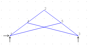
A scissor truss provides an example of how master-slave constraints are used (this is a plane frame structure because there is bending moment in the members). Each chord member is continuous at the point where the web member meets it and there is a pin connecting one web member to the other at the point where they cross. A new node is introduced in each web member at this point. One of these is a slave for the X and Y translational degrees of freedom, and the other node is the master.
The diagram shows the model before the master-slave constraints are input. To complete the model, take these steps:
Click here to download archive file for this example (Scissor.arc - 2K).
Instability occurs if a structure or a part of it can move without any resistance. In this case no solution can be obtained. Ill-conditioning occurs if a solution is obtained but with severe loss of numerical precision. An ill-conditioned structure is usually one which is almost unstable, producing gross displacements during analysis. Ill-conditioning may also occur if there is an excessive difference in stiffness from one part of the structural model to another.
Instability and ill-conditioning are properties of the structure, not of the loading condition. They are usually caused by insufficient node restraints, too many member releases or inappropriate values for some section properties. The most common error conditions are described in this section. See also "Common Modelling Problems".
If insufficient supports have been specified for overall stability of the structure, analysis is not possible. This condition will be detected before analysis is started and an error of the following form will be reported:
STRUCTURE HAS INSUFFICIENT SUPPORT
Case 1 in the diagram below shows a simply supported beam with insufficient support.
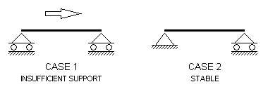
INSUFFICIENT SUPPORT
If there is zero stiffness for any degree of freedom (DOF) at any node a force or moment could be applied at that DOF without any resistance and so it would be impossible to calculate a displacement in that direction. These errors are detected at an early stage of analysis and reported with an error of the form:
ZERO STIFFNESS AT NODE nnnnn DOF f
where
nnnnn = The node number at which instability was detected.
f = The DOF number in which there was found to be no resistance to displacement.
1 - X direction
2 - Y direction
3 - Z direction
4 - about X axis
5 - about Y axis
6 - about Z axis
A node where a zero stiffness error occurs may be referred to as an unstable node. Unstable nodes can be eliminated by applying a restraint to the zero stiffness DOF at the node. An unstable node is shown in Case 1 in the diagram below. Nodes are represented as solid blocks.
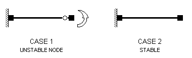
ZERO STIFFNESS AT NODE
If a structure has any part which can move freely it is actually a mechanism and cannot be analysed. A mechanism will be detected during analysis as an attempt to perform impossible numerical operations at a particular DOF and one of the following errors will be reported:
STRUCTURE UNSTABLE AT NODE nnnnn DOF f
or
ZERO PIVOT AT NODE nnnnn DOF f
where "nnnnn" and "f" are as defined above.
Mechanisms may be eliminated by applying a restraint to the DOF reported in the error message but you should consider whether the error is a symptom of a more fundamental problem with the structural model such as a missing support, an inappropriate section property value or an incorrect member release.
A mechanism is shown in Case 1, in the diagram below, where the frame has pinned supports and also has pins at the top of each column. If any one of the four pins were removed, the structure would be stable.
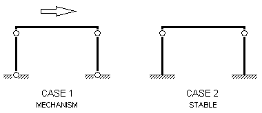
MECHANISM INSTABILITY
Zero stiffness at a node in a direction which is not parallel to a global axis is also detected as a mechanism during analysis. This type of instability cannot be eliminated by specifying a restraint (in a global axis direction) but by adding a link member or a spring in a non-global axis direction.
If severe loss of numerical precision occurs during analysis the structure is ill-conditioned. The condition number, reported on the screen after analysis, is a measure of how much precision was lost. When an analysis has been completed with a large condition number being reported, the results should be regarded as being meaningless and the structure may well be unstable. A displaced shape plot of an ill-conditioned structure would usually show gross displacements. Microstran does not arbitrarily decide at what point the ill-conditioning becomes unacceptable so that the user should always check the condition number (see "Report Contents").
After analysis Microstran performs an equilibrium check in which the external forces are compared to the sum of the member forces at each node. If this check shows a discrepancy the following error message will be reported:
LARGE RESIDUAL - POSSIBLE MODELLING ERROR
In this case, a large condition number will also be reported and the results should be regarded as being meaningless. Note that it is possible for ill-conditioning to occur without a discrepancy in the equilibrium check – a satisfactory equilibrium check is not a guarantee that the analysis was successful.
Sometimes, it may not be evident that a single member has been input instead of two or more connected end-to-end. If this occurs, it can give rise to unconnected members at the interior nodes. In the diagram below, for example, if the rafter is input as a single member (2-4) from node 2 to node 4, the central column will not be connected to the rafter and it will be unstable. The rafter must be input as two members, 2-3 and 3-4, so that the central column (6-3) is connected to it.
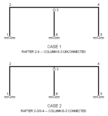
UNCONNECTED MEMBER
If zero stiffness errors are reported at nodes in a plane truss it may be because the structure type is set to "plane frame" while all members are pin-ended. This situation may be avoided by any of the following procedures:
A situation where a zero stiffness error will occur in a plane frame is illustrated in Case 1 in the diagram below. In Case 2, where at least one member is rigidly connected to the node, there is no instability. The node is represented in this diagram as a solid block.
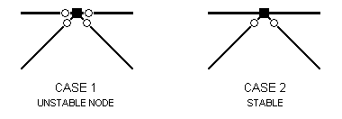
CONTINUOUS CHORD IN PLANE TRUSS
Pin-ended members may also be modelled by specifying a zero for the appropriate section moment of inertia so that the member has no flexural stiffness. In this case, moment releases are unnecessary and should not be used. This modelling technique cannot be used if transverse loads are applied to members, if there are acceleration loads or if you are using non-linear or elastic critical load analysis.
In a space truss (where all members are pinned at both ends), the structure must be fully triangulated to be stable. Any node in a space truss where all connected members lie in a plane is known as a coplanar node and will be unstable unless there is a restraint or a spring support or a master-slave constraint which inhibits displacement normal to the plane. In the Microstran checking phase, warning messages are issued for all coplanar nodes detected.
Consider, for example, a tower structure modelled as a space truss (see "Example 3 – Space Truss"). Each face panel of the tower will be a plane truss and although it may be stable in its own plane, out-of-plane displacement of the interior nodes of the truss must be inhibited to make the model stable. If the analysis proceeds with any instability of this type existing, a zero stiffness error will occur if the plane is parallel to a global plane. If it is not, instability or ill-conditioning will be reported during analysis.
When very stiff structural elements are being modelled, unreasonably large values should not be input for section properties. For example, when modelling a wide column, a very stiff link member may be used to connect a node on the centre-line with a node on the face of the column. While a value for the moment of inertia of the link of 10E3 times the moment of inertia of the column may yield satisfactory results, a value of 10E20 times that moment of inertia would cause ill-conditioning. This kind of modelling problem can be eliminated altogether by the use of rigid member offsets (see preceding section and "Rigid Member Offsets").
| Applies To | |||
| Product(s): | Microstran | ||
| Version(s): | V8i | ||
| Environment: | N/A | ||
| Area: | Analysis | ||
| Original Author: | Richard Collins | ||
Non-linear analysis is very much more computationally-intensive than linear analysis. The time required for linear analysis is much the same whether there is one load case or several, but with non-linear analysis, each analysis iteration of each load case takes about the same amount of time as a linear analysis for one load case. Thus, it is usually worthwhile skipping load cases for which results are not required.
In linear analysis superposition is used to calculate the results for combination load cases but in non-linear analysis this may not be valid. The results for a combination load case are obtained in non-linear analysis by adding together all component load cases and then performing the analysis for the combined loads. In effect, it would be wasted effort to analyse a load case which cannot exist on its own. For example, wind load cases cannot exist without concurrent dead load so there is no point performing a non-linear analysis of a wind load case.
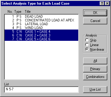
During non-linear analysis, selected load cases may be analysed with linear analysis. This is necessary, for example, when designing some steel members to AS 4100 and others to AS/NZS 4600 - non-linear analysis is used with the former and linear with the latter. When the Analyse > Non-Linear command is selected a dialog box appears showing all existing load cases. This dialog box is shown below. An analysis option indicator is shown for each load case - this may be S (Skip), L (Linear), or N (Non-linear). Select the required analysis option and then click on the load cases to be marked with this analysis option.
When analysing large structures you may be able to save a significant amount of computer time by clearing the Node coordinate update check mark, as shown in the Non-Linear Analysis Parameters dialog box below.
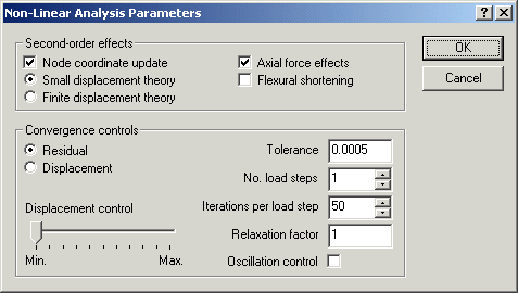
With these settings, full account is taken of the effects of axial force on member flexural stiffness while the effects of node displacement are approximated by a sidesway correction in the stability function formulation. These settings normally provide the quickest solution where second-order effects must be taken into account. You should check that the results agree with those obtained with both Node coordinate update and Axial force effects selected.
When designing steel members to AS 4100 or NZS 3404 you may find that you can use linear analysis instead of non-linear analysis for all but the final design. These steel design modules automatically use moment amplification when results have been obtained with linear analysis. Where the computed moment amplification factor exceeds 1.4 for any member, however, the design cannot be performed.